ARCH653
College of Architecture
Texas A&M University
Ahmed Mezaien
Fall 2017
Project 1
Project 1

Al-Bahr Towers, Abu Dhabi, United Arab Emirates
The project designed by Architect Abdulmajid Karanouh + Diar Consult in 2008
And it built-in 2012
The building Height is 147.0 m include 27 Floors
Project Description
In Al-Bahr towers, the main idea of the project is to design a project to be a landmark building in Abu Dhabi, United Arab Emirates, by integrating modern design and modern technology for that specific region.
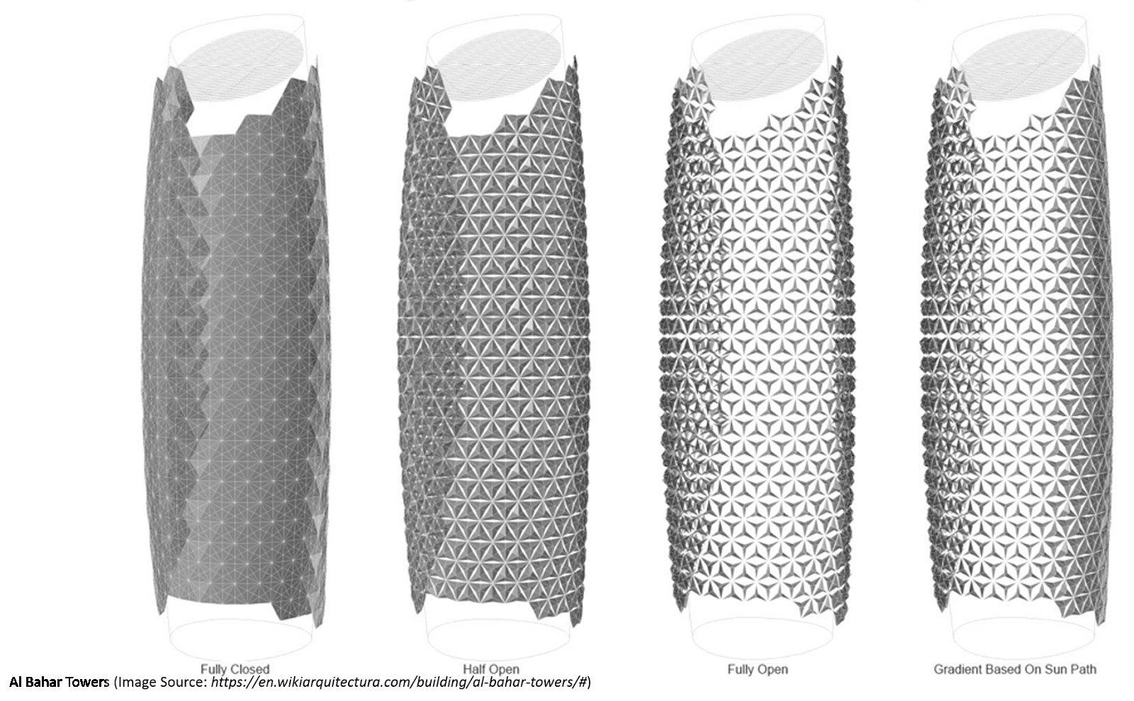
The design consists of a primary geometry form, which is almost two cylinder towers beside each other. However, the unique idea is meant to reduce solar heat gain, which can come from the façades, through the adoption of the “mashrabiya,” a window screen from Islamic architecture, and to reform the design into an umbrella shape with a parametric design. Each shading module can open and close by responding to the sun's movements.


Step 1
Create a parametric, conceptual mass family for your building


• Get started with modeling cylinder towers by using conceptual mass tools in Revit, and use the floor plan to create that building mass.
· Then, create three work planes to draw 3 circles with different diameters to give this cylinder form.
• Then, create void forms to make this angle on the top of this building.
• Then again, use the same work planes to draw 3 curves to create another form for creating the pattern panel units, and divide the surface to be triangles.
· Create new parameters and input the formulas
U= (sqrt(3) /2) * Base Level
V= Base Level / 2
______________________________________________________________________________ Step 2
1- After I made the conceptual models. I created the modules unit in separate file.

 ______________________________________________________________________________by opening new family => conceptual mass (to make the triangle) =>
Create line => extrude the line to the top to be a surface => divide surface and choose (triangle flat)
In properties window, change U and V grid “layout “to “fixed distance”
Pattern unit:
1- New family=> choose “curtain panel pattern based “
2- Select the grid to match the original surface from your previous work, and choose “triangle flat “
3- Make sure there are three points (dotes)
4- Open google and find the formula by looking at “Equilateral Triangle “
______________________________________________________________________________
Step 3
1- Add new parameter and name it “Base Level” that for the triangle
2- Add the formulas to “U grid “and “V grid “by click to “distance” from properties window
Base level= 10
 V grid = = Base Level/2
Step 4
1- click on grid and change “ vertical spacing “ to match the triangle base from the original surface which you are already created previously
Diagrams:
Open Condition Semi Closed Condition Close Patterns Condition

Figure 1
Al Bahar Towers remodel in Revit by Ahmed Mezaien, 2017. (Source: Ahmed Mezaien)
Step 5
1- Divide every line of the triangle by adding “point element “in the center of each line. (Make sure you are in” draw one face “ )
2- Choose “adoptive point #2 “and choose the other point and draw “spline through points “
4- Repeat the process for the other adaptive point # 1 and #3
1- Choose “set” plane to draw dimension pattern the adaptive point 2 and 3 (select the points)
Step 6
1- Add a new parameter from “family type” => name it “a” => choose “instance”

 2- Add the formula which is you did - U grid
4- (From Wikipedia “equilateral triangle” you can find the center of the equilateral triangle by looking to the formula
R= h/3 (the radius of the inscribed circle)
5- Add a new parameter and name it “h” => choose “instance” => add a formula
H = a/3
6- Add a new parameter and name it “NCP” => “number curve * parameter” => choose “instance” => change length to “number” add the formula “h/a” to know the percentage
7- Click the new point and look at properties window => dimensions => measure form “end”
8- Normalized curve parameter => sign to parameter “number curve parameter” to be in the center
Step 7
Work on the panel
Step 8
1- Create another “point element”, but go to “option bar” => placement plane => “pick” => go to center point and by “tab click” choose the “horizontal plane” and click over => you will get the warning but click “ok” => move to the up
2- In properties window => dimensions => offset => associate family parameter => choose “a”
4- Add a new “point element” in last reference line
6- Repeat the process point #2 and the center point
7- Make 2 new point element in the last 2 reference you just created it
9- Select the new point element in the base => properties window => dimensions => normalized curve parameter => associate family parameters => add a new parameter => name it “Number Curve Parameter or NCP” choose “instance” measure from “end” => that will be useful when panel move

Step 9
1- Add a new parameter and name it “LH” => choose “instance” => add the formula
LH = | = H * (1- NCP)
2- Select the same new moving point from the base and select the center point => draw “spline through points”
3- Add a new parameter name it “PA” => choose “instance” add the formula
PA = | = sqrt [(H^2) - (LH^2)]
4- Select the new point on the vertical line reference => dimensions => normalized curve parameter => associate family parameter => add parameter => name it “pA_NCP” => choose “instance” => number => add the formula
PA_ NCP = | = PA / A
5- Change NCP to test it
6- Repeat the same process for that another side to draw “spline through points” only
7- Add a new parameter and name it “HR” => “instance” add the formula
HR= | = A - H
8- Add a new parameter and name it “HR_Base” => “instance” add the formula
HR_Base= | = sqrt [(HR^2) - (PA^2)]
9- Add a new parameter name it “HR_NCP” => “instance” => number
Add the formula => to know the percentage
HR_NCP= | = HR_Base / HR
10- Select the point from the base and go to => normalized curve parameter => “HR_NCP”
11- Select the bottom new points and make a new reference line
12- Select all the reference to create a form
13- In properties window => construction => positive offset=> associate family parameter => add a new parameter => name it “parameter thickness” =2
14- Change NCP to taste it
Step 10
15- Repeat the selecting process to match the triangle from the another side to make reference
16-Add a new point
17- Change the “measure from end “
18- Repeat all the steps to make the other side of the triangle geometry; that will be easiest part because you already have the parameter ready, you don’t have to do the math again
______________________________________________________________________________
19- Be careful to the position of the point to choose “beginning or end” based on close to zero or one
Step 11
1- Change material after (check filter), only leave panel “check in”
2- Add parameter for material name it “pattern material” => “type”
3- Choose material
To make the structure:
1- Make a half circle by drawing on plan
2- Make another half of the circle
3- Create a new form to make the structure
4- Choose the pattern change
U grid rotation + number
V grid rotation + number
_____
Step 12
Making the structure frame
1- Open new family => c* panel pattern based => Change the pattern to “hexagon” => input the horizontal spacing = 10
Input the vertical spacing = 6
2- Draw “point element between 1 and 2” => go to properties => graphics => show reference => “always” => select the point => draw a circle for aluminum
3- Save it with new name => load it to the project

Image: This screenshot to show the structure frame in a separate family file then I load it to the model.


Image: This screenshot to show the structure frame in a separate family file then I load it to the model.

It defined the parameters to be capable of changing the size of these hexagon units
______
Make a separate geometry from to create floors
Bibliography
1. Equilateral triangle. https://en.wikipedia.org/wiki/Equilateral_triangle
2. Roh J. 20150212 computational practice lab 06 091. https://www.youtube.com/watch?v=o1c-4Vfxlcs&t=3747s. Updated 2015.
Al Bahar Towers
remodel using Revit
by Ahmed Mezaien, 2017
by Ahmed Mezaien, 2017

Image: Changing the parameter values to create different conditions.
A. Open Condition
B. Semi-Closed condition
C. Closed Condition

Image: Sun Study through one day June 21st 9 AM, 12 PM and 4 PM

Image: Exterior view to show the responsive façade

Image: 16th-floor details include shading modules, curtain wall, interior walls, doors, furniture, floor, and ceiling

Image: Exterior view to show the responsive façade

Image: interior view to show shading modules into semi-closed condition

Image: interior view to show shading modules into closed condition
This project was a good exercise, and it helped me use the skills that I learned in BIM class, with the Revit software, to design and remodel parametric design ideas for responding facade in buildings. I can say that I had some similar experience in developing a parametric design façade in some of my earlier studio projects, and the Al-Bahr towers project has inspired me to design that parametric design façade in my previous studio. However, the difference is I was using “Rhino and Grasshopper” for my design, which primarily dealt with geometry modeling, and I never used equations and formulas in that software, unlike with Revit.
Also, I am looking forward to the next part of the project to create and design a building by using Dynamo in Revit and apply that design technique to make the pattern panels capable of moving by responding to the sun’s movement. After part two, I will have a complete idea of how to compare these two modeling tools, Dynamo in Revit and Grasshopper in Rhino.
---------------------------------------------------------------------------------------------------
---------------------------------------------------------------------------------------------------
Project 2

Project Description
Based on Project 01 and using BIM methods in Revit, I was able to create and complete remodeling of parametric design ideas for the Al-Bahr Towers which call for responsive facades in the buildings. By continuing to work on the same building for Project 02 using Dynamo in Revit, I am looking to give each panel a different opening or closing shape, which can be based on the sun’s movement. On the other hand, I am also looking to redo every parametric design technique that I applied in Project 01 using BIM tools, such as panel movement, hexagonal structures, and building sizes, but this time using Dynamo in Revit. There will be a benefit to learning another technique for building information modeling using Dynamo in Revit. After Project 02, I will have a complete idea for comparing these two modeling tools, Dynamo in Revit and Grasshopper in Rhino software.
- In project 02 by using Dynamo, I was able to complete three tasks include:
1- I created a definition to resize the panels shape to make it big or small.
2- I created a script that can change the color of the panels based on an image (pixels).
3- I made the panels change to be opened, closed or semi-closed based on the sun's movement.
Al Bahar Towers
remodel using Dynamo - Revit
by Ahmed Mezaien, 2017
Steps:


1- Resize the panels shape


Images: the screenshots are showing the modeling process in Dynamo

Image: this screenshot to show the definition of resizing the panels shape
2- Coloring the panels based on the image


Images: the screenshots are showing the modeling process in Dynamo

Image: this screenshot to show the definition of coloring the panels based on the image
3- Building facades change based on the sun's movement


Images: the screenshots are showing the modeling process in Dynamo

Image: this screenshot to show the definition of how building facades can change based on the sun's movement


Image: interior view to show shading modules within responding to the sun
Your blog on architectural visualization is insightful and well-structured! The role of an architectural physical model in bringing design concepts to life is invaluable. Combining physical models with digital visualization enhances precision, helping architects refine spatial dynamics effectively. Your perspective on integrating both techniques is truly inspiring—keep sharing such valuable architectural insights!
ReplyDelete